by Bart Stockdill, M.A.Sc., P.Eng., Mechanical Engineer
Water will boil at room temperature if the pressure is low enough. In fact, the pressure has to be very low, about 2% of standard atmospheric pressure at sea level.
Just like a wing generating lift, marine propellers use pressure differences across their blades to generate thrust. The pressure distribution on a propeller blade depends on its shape and how that shape influences the speed of the water flowing
around the blade. As the flow speeds up, the pressure drops and conversely when the flow slows down, the pressure rises.
Thus the blade is shaped to promote higher speed on the forward or suction side and lower speed on the aft or pressure side. If the blade shape is too aggressive, very low pressure can result. Indeed, this pressure can be low enough to reach the boiling point of water which then leads to cavitation.
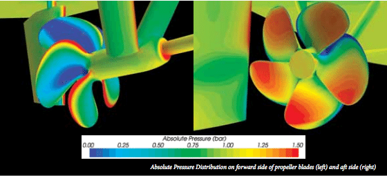
In the figures above, the pressure distribution on the propeller of a semi-displacement hull is shown at 18 knots and 1200 rpm. The low pressure areas on the forward side of the propeller are shown in blue in the left figure. The high pressure areas on the aft side of the propeller are shown in orange on the right. Since the hydrostatic pressure increases with depth below the water surface, the pressure on the bottom half of the propeller is slightly higher than the top half.
The pressure plots show a problem with this propeller near the leading edge of the blades. There is a narrow band of high pressure (red area, left) on the suction side and a narrow band of low pressure (blue area, right) on the pressure side. This is undesirable since it means that the leading part of each blade is generating thrust in the wrong direction!
There is one catch though: these pressure plots do not include the effect of cavitation. The dark blue areas show pressure below the vapour pressure of water which means cavitation should occur in those areas. By turning on the cavitation model, the phase change from water to water vapour can be captured. This is shown in the figure at the right where the pink area represents the interface between water and water vapour. The remarkable accuracy of this cavitation prediction can be seen by comparing the areas of erosion on the actual propeller (left) with CFD results (right).
The model shows that sheet cavitation is occurring near the leading edge on the pressure side of the blades. This indicates that effective angle of attack near the leading edge must be negative, resulting in an area of very low pressure on the aft side of the blade.
The erosion damage to this propeller occurred after only 500 hours of service. By using CFD analysis, the nature of the cavitation and the hydrodynamic conditions that are causing it have been identified. Now the propeller design can be modified and the performance of the new propeller verified using the same approach. This reduces the potential for
additional propeller modifications that are sometimes necessary when using traditional design methods.
by Kevin Hamilton (University of Hawaii) In 2021, an expedition off the icy northern Greenland coast spotted what appeared to be a previously uncharted island. It was small and gravelly,...
(Bloomberg) –A self-described fan of Tesla Inc. said he was behind an application to extend the automaker’s trademark for use in boats and planes. The Dec. 28 filing with the US Patent...
Editor’s Note: This article was originally published by gCaptain in 2016 and is being republished now because it’s lessons are timeless and possibly more relevant in 2022 as today’s ships...
November 27, 2022
Total Views: 5286
Why Join the gCaptain Club?
Access exclusive insights, engage in vibrant discussions, and gain perspectives from our CEO.
This website uses cookies to improve your experience while you navigate through the website. Out of these, the cookies that are categorized as necessary are stored on your browser as they are essential for the working of basic functionalities of the website. We also use third-party cookies that help us analyze and understand how you use this website. These cookies will be stored in your browser only with your consent. You also have the option to opt-out of these cookies. But opting out of some of these cookies may affect your browsing experience.
Necessary cookies are absolutely essential for the website to function properly. This category only includes cookies that ensures basic functionalities and security features of the website. These cookies do not store any personal information.
Any cookies that may not be particularly necessary for the website to function and is used specifically to collect user personal data via analytics, ads, other embedded contents are termed as non-necessary cookies. It is mandatory to procure user consent prior to running these cookies on your website.

 Join The Club